
Table of Contents
Software
To run RDC Charger application it is required:
- to establish connection between charger and router by UTP cable
- to connect charger to the power supply
- download and install latest version of application for RDC Charger *
 Once RDC Charger is configured, it does not require further connection to internet or configurator for normal operation !
*Latest version of RDC Charger (EVSE) can be found under Downloads map.
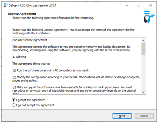
Installation
- run rdc_charger .exe file from Downloads
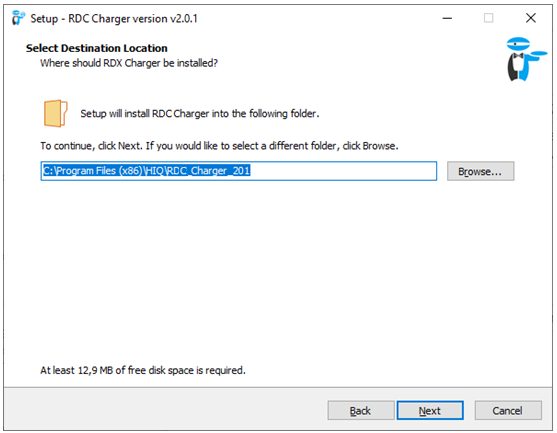
- select default or desired folder
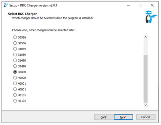
- select charger serial number (SN), visible on sticker *
- run install
*if does not appear a window with SN or it is not listed it means that application at this moment did not recognize charger. Continue with installation and select SN on application later.
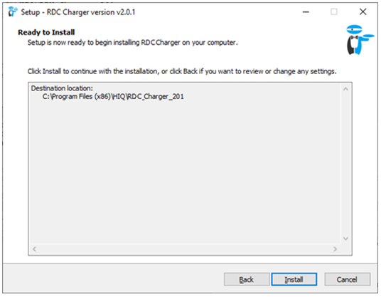
Installation is successful!
EVSE overview
Parameters in blue colour are editable.
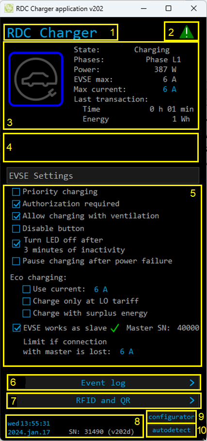


| 1. EVSE Name | |
|---|---|
| Name of EVSE - default is RDC Charger. | |
| 2. DLM sign | |
| | Yellow status when DLM is enabled and active. Green status when enabled and not active. None if DLM is not set. |
| 3. Data from ongoing charging session | |
| EV charging icon with LED light | Different LED light colour is presenting charger state, while icon acts as a button. Short press toggle enable/pause charging, long press for priority charging and error reset. |
| State | EVSE status: Communication error; Unknown; Available; Preparing (authorization done, waiting for vehicle to be connected) or (EV connected, authorization required); Charging; SuspendedEV(Paused by EV); SuspendedEVSE(Paused by EVSE); Finishing; Fauled(error); Unpausing; Unavailable; No EVSE response; Available, Authorisation required; Stopping; Starting; Suspended by DLM; Reserved; Reserved, preparing(EV connected, authorization required); Charging ended or suspended by EV |
| Phases - number of used phases while charging | 3 phases, Phase L1, Phase L2, Phase L3, Unknown phase, 2 phases. |
| Power | Charging power of EV. |
| EVSE max | Momentanely the maximum allowable charging current |
| Max current | Allowed max charging current. |
| Last session | Time - duration of charging session, Energy - consumed energy of charging session. |
| 4. Error message(s) | |
| Possible errors are: CP positive voltage; CP negative voltage; RCD sensor trip; Overvoltage; Undervoltage; Charge with ventilation; PS reading error (EVSE); Current is higher than allowed; RCD sensor malfunction; Internal temperature is too high; PS reading error (grid); Can not lock; Can not unlock; Socket temperature is too high; Unavailable; Other error Note: for resolving errors please see table below. |
|
| 5. EVSE settings | |
| Priority charging | Utilize all available power to charge as fast as possible ignoring eco charging. |
| Authorization required | Disable unauthorized use of EVSE, authorization is possible with RFID Card, QR code or by cloud application. |
| Allow charging with ventilation | Allow/deny charging if EV requests ventilation. |
| Disable button | Disable functionality of button on housing. |
| Turn LED off after 3 minutes of inactivity | LED light is turned off after 3 minutes. |
| Eco charging | Use current: set desired current for charging. Charge only at LO tarriff: charging possible at low tariff only. Note: LO tarriff must be set. Charge with surplus energy: dynamically charge EV if there is surplus energy |
| EVSE works as slave | EVSE is a slave to master (Modbus TCP communication) EVSE with its serial number-SN. Green tick if communication is OK, red X for lost communication. |
| Limit if connection with master is lost | In case of lost communication, use set charging current. |
| 6. Event log | |
| Shows last 10 charging session. | |
| begin & end time | Begin date, hour and end of charging session. |
| duration | Duration of charging session [h:min]. |
| energy | Consumed energy in session. |
| card nr./type | Card ID used for charging session. If note “not locked” card ID is not used/needed. |
| note | Status message about charging session (normal or some error). |
| 7. RFID, MIFARE and QR | |
| Add or delete RFID/MIFARE tag or QR code, for managing authorized access to EVSE. | |
| Card no. & card ID | Supported up to 10 RFID/MIFARE/QR tags/cards. |
| Manage card | Press Add for new card or delete existing one. |
| Time | 60 seconds time frame for adding new card. |
| 8. Time & date and SW version | |
| Time and date with software version release. | |
| 9. configurator | |
| Runs Configurator | |
| 10. autodetect | |
| Click to find EVSE in local network | |
Error table
RDC Charger recovers error automatically. To delete error by yourself long press button on charger housing or on application. Charging is stopped while error is active. If red light still flashes, please read table bellow.
| Error | Possible causes | Possible solution |
|---|---|---|
| CP positive voltage CP negative voltage | Measured voltage on CP pin is out of range. | Check your charging cable and plug. Reconnect your EV. If error still appears, please contact your EVSE service. |
| RCD sensor trip | DC current leak detected. | Please try to connect another EV, if error still appears, please contact your EVSE service. Otherwise, please contact an authorized car service department. |
| RCD sensor malfunction | RCD sensor is damaged or not connected. | Please contact your EVSE service. |
| Undervoltage Overvoltage | Supply voltage is out of range. | Please contact your EVSE installer. |
| Charge with ventilation | EV requests charging with ventilation and “Charging with ventilation” is not enabled on configurator. | Enable “Allow charging with ventilation” if charged EV is located in ventilated area. |
| PS reading error (EVSE) | No communication with internal power sensor. | Please contact your EVSE service. |
| PS reading error (grid) | No communication with grid power sensor. DLM can not work properly. | Check connection with grid power sensor. Please contact your EVSE installer. |
| Current is higher than allowed | Vehicle draws more current/power than allowed. | Please try to charge another EV, if error still appears, please contact your EVSE service. Otherwise, please contact an authorized car service department. |
| Internal temperature is too high | Temperature inside of charger is too high. | Make sure charger is not exposed to direct sunlight. Please contact your EVSE installer. |
| Can not lock | Only for charger with socket: Socket can not lock the connected plug. | Unplug the cable and check if the plug is clean. If it's clean, try charging with a different cable. If it still doesn't work, contact the EVSE installer. |
| Can not unlock | Only for charger with socket: Socket can not unlock the connected plug. | Unplug the cable on the vehicle side and try again. If it doesn't work, contact the EVSE installer. |
| Socket temperature is too high | Only for charger with socket: The socket is overheating, socket pin temperature is too high. | Try different solutions: 1. Unplug the cable and check if the plug is clean. 2. Turn off the power supply to the charger and check if the socket is clean. 3. Try charging with a different cable. If it doesn't work, contact the EVSE installer. |
| Unavailable | Parent system has set the charging station to “unavailable” status; Usually for system maintenance or upgrades. | Wait for the upgrades to complete. If it takes more than 5 minutes, contact EVSE service or your parent system provider for information. |
| Other error | Other errors that can not be resolved by the user. | Contact EVSE service. |
HEMS Configurator
home
Basic system overview.
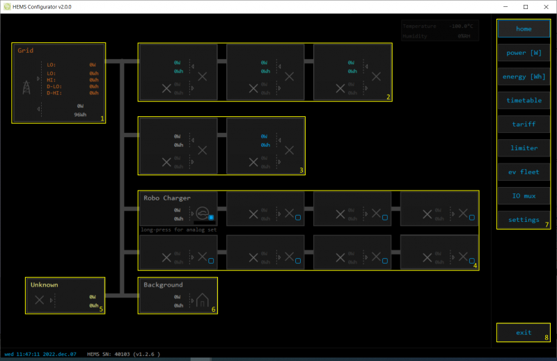
| 1. Grid | ||
|---|---|---|
| › | From grid | Tariff (LO, HI, D-LO, D-HI) and power from grid in W |
| Imported energy by tariff in Wh | ||
| ‹ | To grid | Power exported to grid in W |
| Exported energy in Wh | ||
| 2. Plants | ||
| ‹ | Produced | Produced power in W and energy in Wh |
| › | Consumed | Consumed power in W and energy in Wh |
| 3. Storage systems | ||
| ‹ | Sourced | Power in W and energy in Wh sourced from storage (battery) |
| › | Stored | Power in W and energy in Wh stored (to battery) |
| bargraph and %¹ | SOC | Battery State Of Charge |
| 4. Consumers | ||
| › | Consumed | Consumed power in W and energy in Wh |
| [] | Status | Output status for managed consumers |
| click | Toggle | Click in frame toggles managed consumers output |
| 5. Unknown source | ||
| › | Sourced | Power in W and energy in Wh from unknown source |
| Accumulate also all differences caused by power sensor inaccuracy |
||
| 6. Other consumers | ||
| › | Consumed | Consumed power in W and energy in Wh by other (not measured) consumers |
| 7. Page navigation | ||
| home | Home screen | |
| power [W] | Power screen | |
| energy [Wh] | Energy screen | |
| timetable | Timetable screen | |
| tariff | Tariff screen | |
| dlm | Limiterscreen | |
| ev fleet | EV fleet screen | |
| IO mux | IO mux screen | |
| settings | Settings screen | |
| 8. Exit | ||
| exit | Close appliction | |
¹ only for eStore
power
Overview of current power distribution by source / consumer.

| 1. Sourced power |
|---|
| Sourced power for each source |
| Sums per source type |
| Total of all sourced power |
| 2. Consumed power |
| Power for each consumer |
| 3. Power distribution |
| Partial distributed power |
| 4. Submeter (Green outline) |
| Power meter is not part of internal circuit |

| 1. Sourced power distribution |
|---|
| How sourced power is consumed by each consumer |
| 2. Consumed power distribution |
| Who sources consumed power |
energy
Energy overview of a given time distributed by sources / consumers.
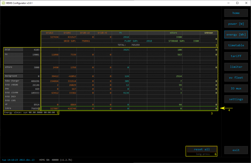
| 1. Sourced energy |
|---|
| Sourced energy for each source |
| Sums per source type |
| Total of all sourced energy |
| 2. Consumed energy |
| Energy for each consumer |
| 3. Energy distribution |
| Partial distributed energy |
| 4. Submeter (Green outline) |
| Power meter is not part of internal circuit |
| 5. Energy since |
| Date and time since energy is recorded |
| 6. Reset all |
| Long-press to reset all energy counters |
timetable
Weekly timetable for managed consumers.
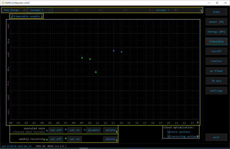
| 1. Managed load menu |
|---|
| Switch between managed loads |
| 2. Enable checkbox |
| When un-checked timetable is not executed |
| 3. Events grid |
| Events displayed in weekly grid (15 min resolution) |
| Click to select time and set event by clicking buttons below |
| 4. Once actions (top priority timetable actions) |
| Actions are executed and then automatically cleared. |
| “Disable” action will just disable recurring action. |
| 5. Recurring actions (low priority actions) |
| Actions are executed each week. |
| 6. Cloud optimization |
| When enabled (checked) cloud optimization is enabled. |
tariff
Weekly tariff timetable for grid energy per tariff distribution.
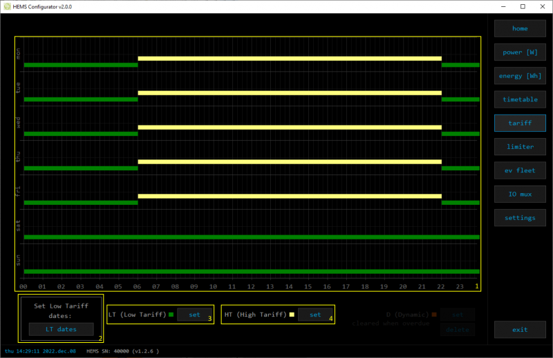
| 1. Tariff grid |
|---|
| Graphical weekly timetable with tariffs. |
| Click to select term, click-and-drag to select multiple terms. |
| 2. Low tariff dates |
| Set low tariff dates for holidays. |
| 3. Low tariff |
| Set low tariff for selected terms. |
| 4. High tariff |
| Set high tariff for selected terms. |
lo tariff dates
Holiday dates when tariff is low
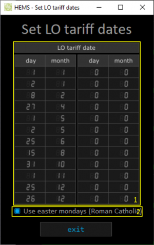
| 1. Date table |
|---|
| Up to 24 days when tariff is low on holiday |
| 2. Use easter mondays |
| Use preprogrammed roman-catholic easter monday holidays |
Dynamic Load Management
Overview and configuration of DLM
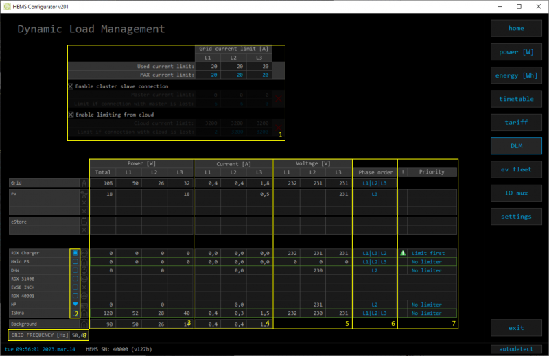
| 1. Grid Current limit | ||
|---|---|---|
| MAX current limit | Current limit threshold for main grid fuse | |
| Enable cluster slave connection | Current limit threshold if charger lost connection with master | |
| Enable limiting from cloud | Current limit threshold if charger lost connection with cloud | |
| 2. Consumer management | ||
| Turn consumers on or off | ||
| 3. Power | ||
| Total power and power for each phase | ||
| 4. Current | ||
| Current for each phase | ||
| 5. Voltage | ||
| Voltage for each phase | ||
| 6. Phase order | ||
| First set correct phase order for grid power sensor and then set for other power sensors/devices. NOTE: changing grid phase order will NOT apply to phase order of other connected devices! | ||
| 7. Status and priority | ||
| | Yellow status when limiter is enabled and active. Green status when enabled and not active | |
| Priority | Device priority group: no limiter, limit last (last to be limited), limit second, limit first (first to be limited) | |
| 8. Grid frequency | ||
| Grid frequency measured on grid power meter sensor | ||
ev fleet
Overview and configuration of EVSE station. Up to 7 external EVSE supported.

| 1. EVSE - RDC Charger | ||
|---|---|---|
| RDC charger | ||
| 2. Additional EVSE (charging station) linked to RDC charger | ||
| EVSE supports up to 7 charging stations. Settings are as for RDC Charger. | ||
| Slave SN: Serial number of slave charger Green tick → control of slave by master is allowed, Red X → control of slave by master is disabled. |
io mux
Overview and configuration of input/output ports IO mux
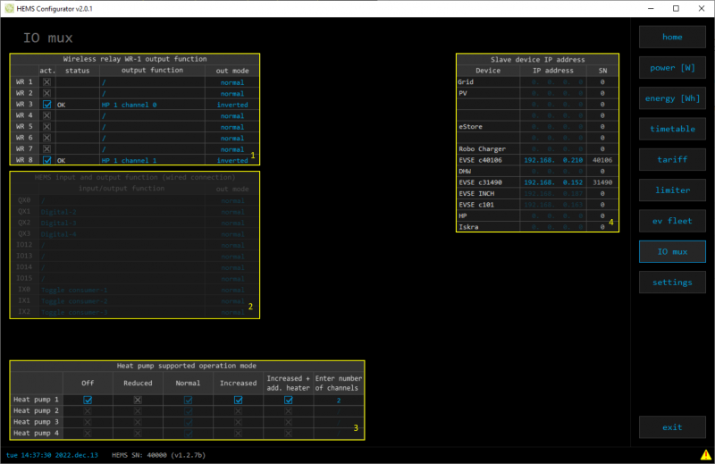
| 1. Wireless relay WR-1 output function | ||
|---|---|---|
| In the left column are WR modules WR-1 (max 8) with corresponding status (active + communication status). To each WR could be assigned HEMS function (e.g. digital, linker reset, router reset, heat pump channel etc) with output mode (normal or inverted). | ||
| 2. HEMS input and output function (wired connection) - not for EVSE available | ||
| In the left column are MC controller ports to which could be assigned MC-230 functions (digital, linker reset, router reset, etc) with output mode (normal or inverted). | ||
| Default settings are for e.g. QX0 → digital 1 while digital 1 is defined for consumer 1 on settings page. Change to define new function role to QX0 port e.g. for linker reset | ||
| Enable consumer at input IX0,IX1 or IX2 means that dedicated consumer will be managed (ON/OFF) by input signal on IX0,IX1 or IX2. For example, if thermostat signal is wired to IXO port and “Enable consumer 1” to IX0, while thermostat is active, consumer 1 is active and otherwise. | ||
| Limitations: one temperature sensor is allowed, one consumer could be managed by one input only. | ||
| 3. Heat pump supported operation mode | ||
| To control Heat pump by EVSE, define supported operation(control) mode based on heat pump specification. E.g. SGRHP supports external control by two channels (Off, Normal, Increased and Increased + additional heater) thus select them in table to enable functionality. Note: Before selecting modes, heat pump must be defined in setting page! |
||
| 4. Slave device IP address | ||
| For device (PV inverter or external EVSE) define its IP address. |
settings
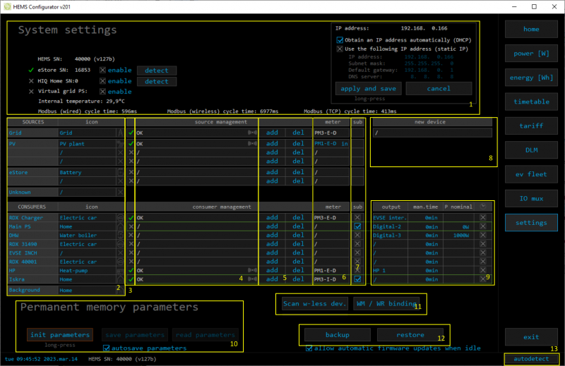

| 1. System settings | ||
|---|---|---|
| eStore | c….. | eStore serial number (automatically detected or can be entered manually). |
| [] enable | When selected EVSE will obtain necessary data (power, voltage…) directly from battery storage system, no need to additional power sensor. | |
| [detect] | eStore address is cleared and new eStore can be detected. | |
| HIQ Home | c….. | HIQ Home serial number (automatically detected or can be entered manually). |
| [] enable | When checked HEMS will read Grid power and energy from HIQ Home (so there is no need to duplicate power-sensor). | |
| [detect] | HIQ Home address is cleared so new can be detected. | |
| Virtual grid PS | [] enable | Select if system is without main grid power meter. Energy, power and currents are calculated from other power meters. |
| Internal temperature | Temperature inside of EVSE | |
| Modbus (wired) cycle time | Cumulative reading time of all wired power sensor in ms | |
| Modbus (wireless) cycle time | Cumulative reading time of all wireless connected power sensor in ms | |
| Modbus (TCP) cycle time | Cumulative reading time of all TCP connected devices in ms | |
| IP address | IP address of EVSE | |
| DHCP | Select for DHCP to obtain an IP address automatically → apply and save to confirm. | |
| Static IP | Set static IP to EVSE → apply and save to confirm. | |
| Note: If static IP settings are wrong, we won't be able to access RDC Charger any more!!! Restart EVSE with jumper between IX1-GND to return RDC Charger to DHCP settings. | ||
| 2. Sources and Consumers settings table | ||
| SOURCES | Source name | |
| icon | Source icon | |
| 3. Device status | ||
| Status | Status OK, Warning, Error, Detected | |
| 4. Device message | ||
| source and consumer management | Source or consumer power sensor management | |
| message | Messages related to source or consumer power sensor | |
 | Power sensor is connected via WM-1 module | |
| 5. Device configuration | ||
| Configuration | add | Associate new power sensor to source or consumer |
| del | Disassociate power sensor from source or consumer & configure it as new power-sensor | |
| 6. Device type | ||
| meter | Source or consumer power-sensor type | |
| configuration | in/ex | Power plant connection¹ |
| 7. Submeter option | ||
| sub | Check if this power meter or device is not part of internal circuit. Energy division for this device is ignored and outlined in green color. | |
| 8. New device | ||
| Detected new power sensor. | ||
| 9. Device output | ||
| output | Select consumer output type | |
| man. time | Managed consumer manual override timer | |
| P nominal | Enter power for device in case where power sensor is not assigned to device. | |
| clock | Enable timetable | |
| 10. Permanent memory parameters | ||
| [init parameters] | Init all parameters to default values | |
| [save parameters] | Save all parameters to permanent memory | |
| [read parameters] | Read all parameters from permanent memory | |
| [] autosave parameters | Parameters will be automatically saved to permanent memory in 15 minutes after last parameter change | |
| 11. WM / WR settings | ||
| Scan w-less dev. | Press to start scanning for power sensors wirelessly connected via WM-1 module as well as for WR-1 relay. Scanning is active for 5 minutes. | |
| WM / WR pairing | Press to pair new WM-1 or/and WR-1. | |
| 12. Backup / Restore to PC | ||
| [backup] | Backup all parameters to PC | |
| [restore] | Restore all parameters from PC backup2 | |
| 13. Autodetect | ||
| [autodetect] | Click to find EVSE in local network. | |
1 only for the first power plant
2 older versions of backup files may be used. Any unsuccessfully backup or restored parameters will be displayed but operation will end successfully if you use continue.
RDC Charger Update
RDC Charger application will detect update automatically.


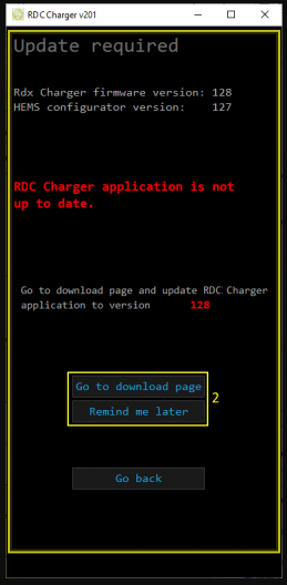
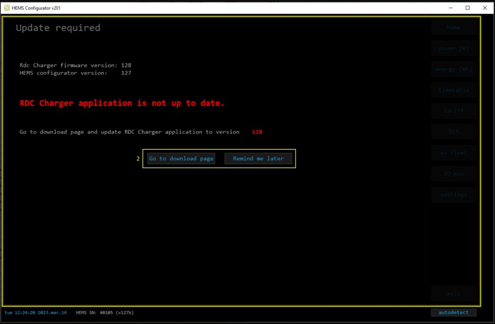
Procedure to update RDC Charger application is as follows:
- press OK and make sure to follow further instructions on page (1) (2)
- hit the button Go to download page (2) which will open internet browser on download page, download and install
- hit the button Remind me later to postpone update for 5 minutes