
wiki:20_rdc_charger:15_hardware:22_wm-1
Table of Contents
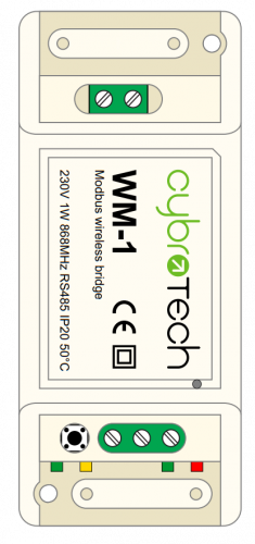
Wireless Modbus-to-Modbus bridge
Wireless Modbus-to-Modbus bridge
| Model number: | WM-1 |
|---|---|
| Frequency: | ISM 868MHz (EU) |
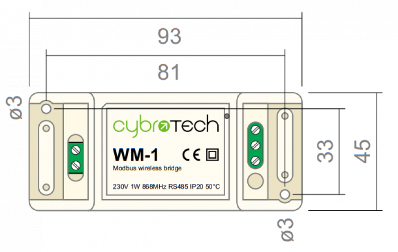
| Dimensions: | 93x45x27 mm |
Applications
- Replacement for RS485 wiring solution with wireless. Optimal for long range Modbus RTU serial communications with half duplex configuration.
Installation and mounting
 Carefully open WM-1 module and configure serial communication with jumpers. (Default configuration is 9600bps, 8N1 with normal timeout)
- Place WM-1 module at least 10cm from other objects. Installation is not recommended inside metal cabinets.
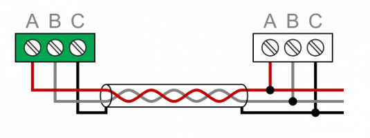
- Connect RS485 terminals to WM-1 RS485 terminals
- A - A
- B - B
- C - GND
- Connect to 230V power supply
- Bind modules to wireless network
Features
- replacement for RS485 wiring
- Modbus RTU serial protocol
- wired/wireless combinations
- very long range, no hopping
- protected private connection
- multiple slaves per device
- multiple addressable groups
Technical specification
| Power supply: | 230V, 50/60Hz, 1W |
| Ingress protection: | IP20 |
| Operating temperature: | -20..50°C |
| Storage temperature: | -40..85°C |
| Relative humidity: | 0..85% n/c |
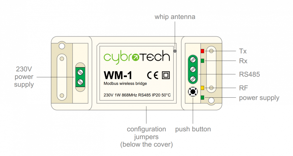
Terminals and wiring
| To power sensor | A | RS485 bus |
|---|---|---|
| B | ||
| C | ||
| To power supply | L | 230V AC |
| N |
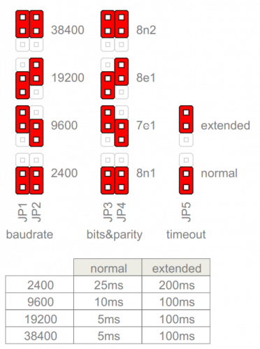
Serial configuration and timeout
- Available baudrates 2400, 9600, 19200, 38400 bps
- Data bits and parity 8N1, 7E1, 8E1, 8N2
- Max 64 bytes per transmition
- Integrated 240 Ohm termination resistor
Wireless binding
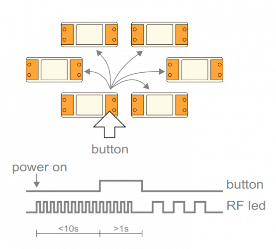
Create new secure group
* turn on all devices at the same time
* within 10 seconds, while RF LED is blinking, press and hold button on one of the devices
* after a second, the new address is randomly generated and sent to all devices. RF LED will blink 3 times to confirm the new address.
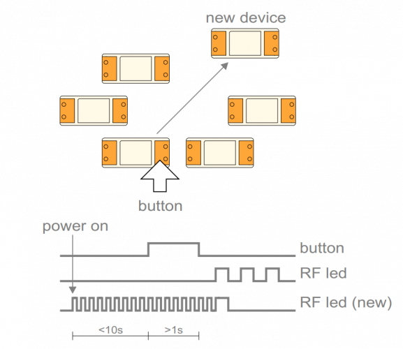
Add new device to the group
* turn on the device
* within 10 seconds, press and hold button on one of the existing devices
* after a second, the existing group address is sent to the new device. RF LED will blink 3 times to confirm the address is sent.
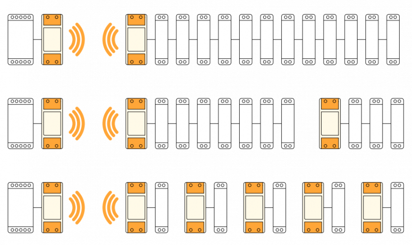
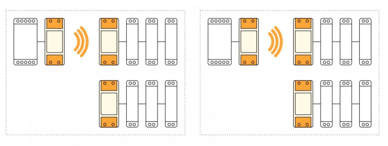
Topology examples
* Modbus master, connected to 12 slaves using a pair of WM-1 devices
* Modbus master, connected to 10 slaves, organized in two groups
* Modbus master, connected to 5 slaves, each one having local WM-1 device
Multiple groups
* When the system has two or more separate Modbus lines, they should be configured as separate groups.
* Each group has a single master and one or more slaves.
* Groups can't talk to each other, but they share the same bandwidth.
* Two masters may start transmitting at the same time causing collisions.
* To reduce number of missed messages, keep the traffic low.
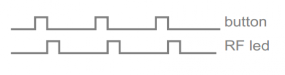
Connection check
- Press button shortly
- RF LED will blink shortly on each connected device
- Serial interface is unaffected
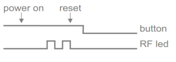
Factory reset
- Hold button and turn the device ON
- RF led will blink twice. Group address is now reset to default.
- Other devices will not be affected.
wiki/20_rdc_charger/15_hardware/22_wm-1.txt · Last modified: by 127.0.0.1