
wiki:20_rdc_charger:25_wiring:start
Table of Contents
Wiring
| Power supply |
|---|
| Depending on the power of the charger, choose the appropriate cross-section of the power supply cable and the appropriate fuse. The connection terminals in the charger enable the connection of a cable up to 10mm2. If you have a charger model without a RCD switch, you must install it before the power supply cable. |
 |
 |
| Network |
|---|
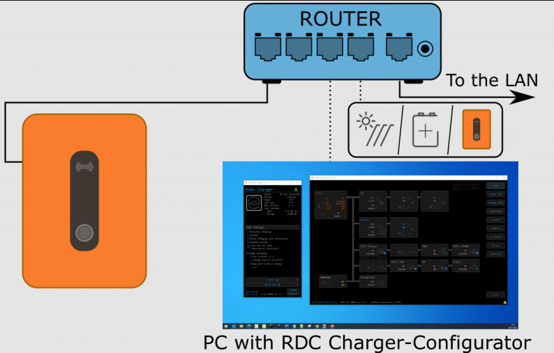
| Default connection to the LAN network: |
 |
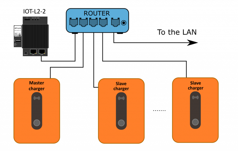
| Default connection of external IOT-L2-2 linker to the LAN network: |
| NOTE: IOT-L2-2 linker can be installed as external unit or is integrated into the RDC Charger. |
 |
| Default connection via LTE 4G modem: |
| NOTE: All connected devices will have internet access via LTE modem which can result in high costs on your LTE account. |
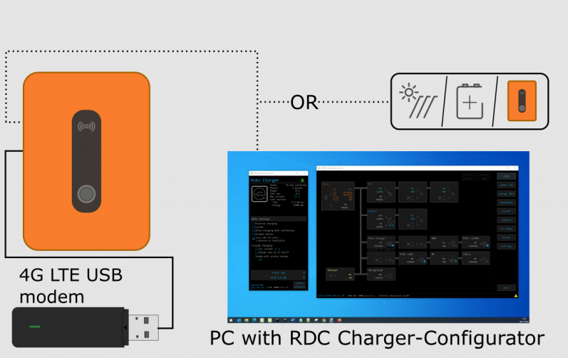 |
| Optional LTE 4G modem connection: |
 |
| EV fleet connection |
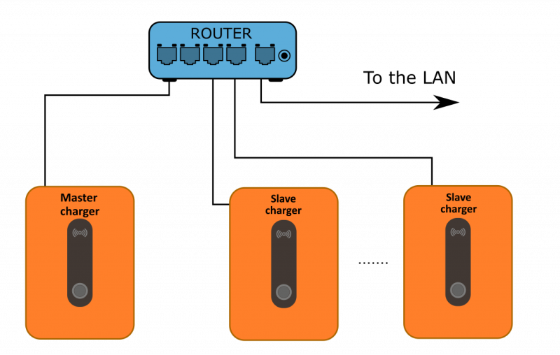
| Control up to 8 RDC Chargers (EV fleet). Only one charger is master, others are slave. All chargers in fleet must be wired with ethernet cable to the same router. |
 |
Wireless Power Sensors wiring
| Wireless power sensors |
|---|
| Single phase power-sensor with current transformer PM1-E-D-CT |
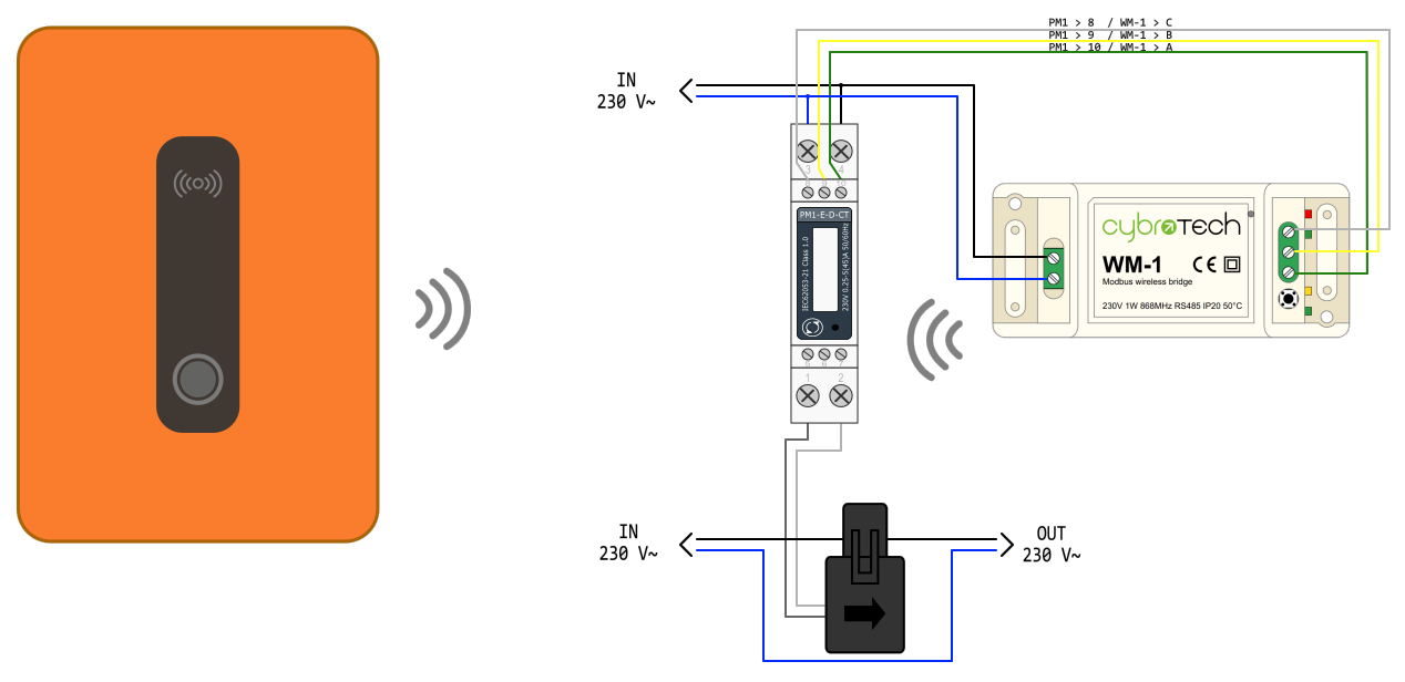 |
| 3-phase power-sensor PM3-E-D |
 |
| 3-phase power-sensor with CT PM3-E-D-CT |
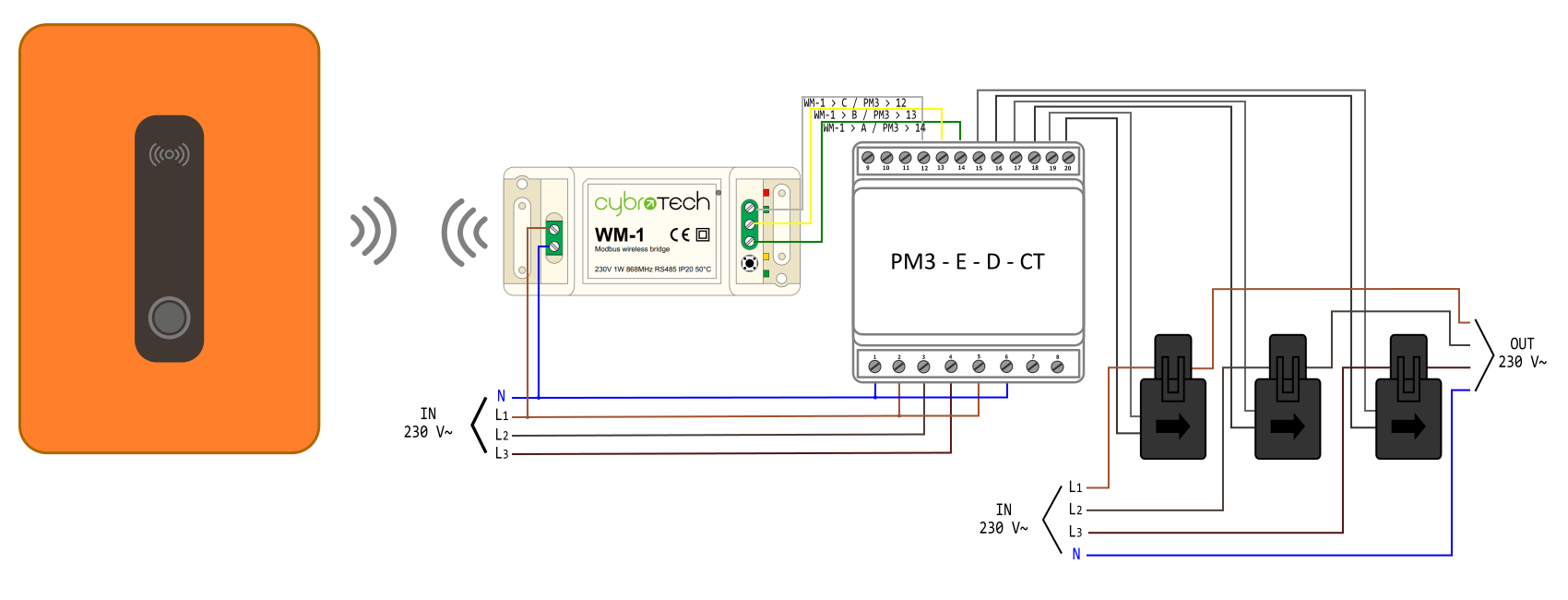 |
| Charger and wireless power sensors. One or more WM-1 modules can be used. One or more power sensors can be connected to one WM-1. |
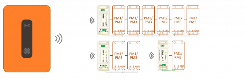 |
| Dynamic load management |
|---|
| Charger and grid power sensor. NOTE Power sensor should be mounted in the building's electrical cabinet to measure input power & current |
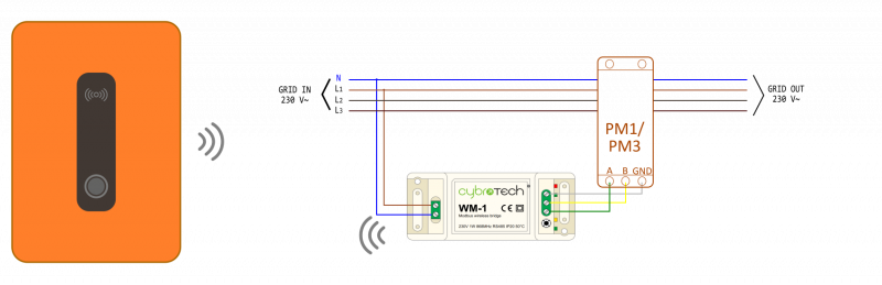 |
Wireless relay wiring
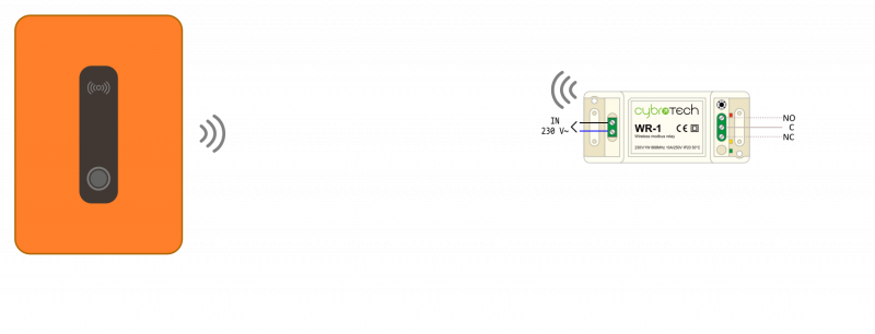
| Wireless relay |
|---|
| Charger and wireless relay. Up to 8 WR-1 modules can be used. |
 |
| Power sensors orientation |
|---|
 |
wiki/20_rdc_charger/25_wiring/start.txt · Last modified: by alen.mejak