Mounting
Before choosing a mounting location, consider the following:
- Do not mount the RDC Charger on flammable building materials
- During operation RDC Charger must not be exposed to high temperatures and direct sunlight
- For better weather protection, we recommend installing protective roof (order code RDC-PR)
- Installation must be vertical
- Wall mounting must be done with appropriate screws (which are included in the package)
- Before installation, you must prepare the power supply and ethernet cable. It is necessary to observe all applicable local and national regulations, laws and regulations governing the installation and use of the EV charging equipment. Depending on the power of the RDC Charger, choose the appropriate cross-section of the supply cable and the appropriate fuse. The connection terminals in the charger enable the connection of a cable up to 10mm2. If you have RDC Charger model without RCD, you must install it before the supply cable to the charger.
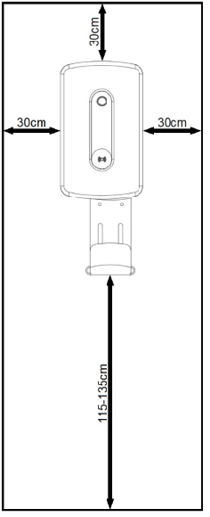
- The recommended mounting height is 115-135cm. (Measured from the floor). If the charger is approximately at eye level, it will be easier to monitor the operation. Leave at least 30cm of space on the left, right and top to ensure adequate ventilation. This will also make installation of the charger easier, and it will be easier to unwind/wind the charging cable.
REQUIRED EQUIPMENT:
- Impact hammer and concrete drill ф 8mm
- Phillips screwdriver PH2 - Screws for fixing the mounting plate to the wall
- SL4 flat screwdriver – Screwing power cables (model without Residual-current device)
- Phillips screwdriver PZ2 - Screwing the power cables on the RCD (model with Residual-current device)
- Allen key 2.5mm (included) - For screws of the plastic cover and for switching the RCD(for models with it)
- Allen key 3mm - For mounting screws the charger to the mounting plate
- Pliers for crimping cable glands and shoes
- Pliers and tools for removing insulation from cables and wires
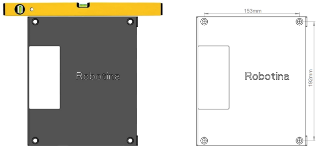
Lean the mounting plate against the wall and mark all 4 holes. Help yourself with the water level.
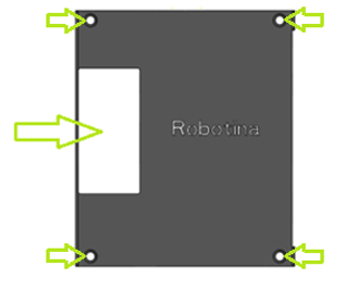
Drill 4 holes with a diameter of 8mm and a depth of 70mm in the marked places and insert the supplied inserts into all 4 holes.
Pass the power supply and ethernet cable through the rectangular opening on the mounting plate. Screw in all 4 screws. (Phillips screwdriver PH2)
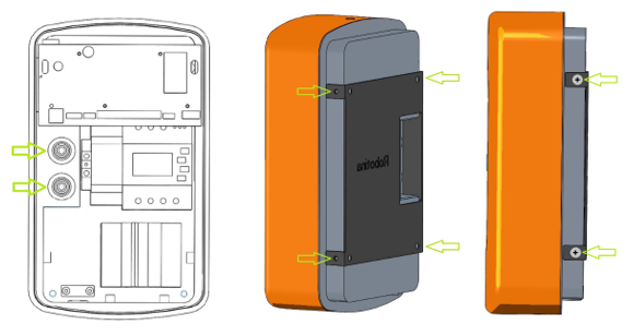
Open the cover and put it down. Thread the power supply and ethernet cable through the rubber plugs. Place the RDC Charger against the mounting plate and screw in all four M5 side screws. (Allen key 3mm)
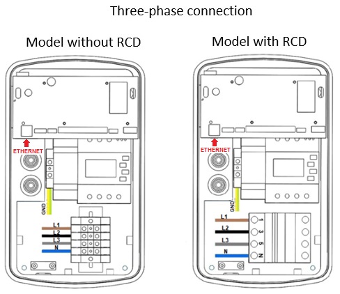
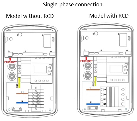
Connect the Ethernet and the power supply cables as shown in the picture below. (For the model with IOT linker, connect the ethernet cable to the IOT linker located on the left side under the pcb) Depending on the power of the charger, choose the appropriate cross-section of the power supply cable and the appropriate fuse. The connection terminals in the charger enable the connection of a cable up to 10mm2. If you have a charger model without a RCD switch, you must install it before the power supply cable.
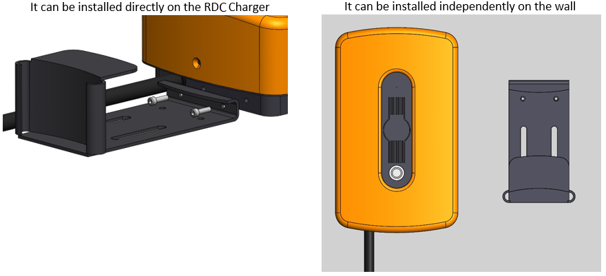
The charging cable holder has two mounting options:
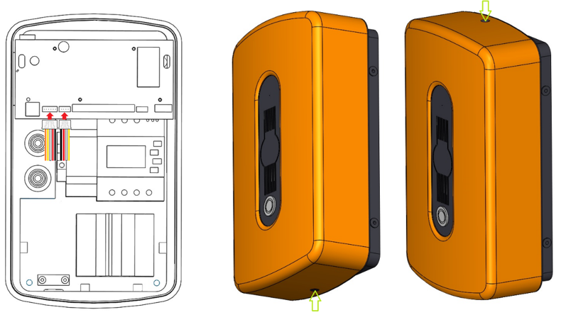
Connect the connectors as shown in the picture below, close the cover and screw in the lower and upper M4 screws. (Included allen key 2.5mm)
